Wireless CAN bus Telemetry using 4G

This project was started last year and continues development on the first prototype. The goal has been to transfer the CAN bus data from our formula car to a web server and a database for easier and live monitoring of the different on board systems, where previously the data has only been accessible by downloading it from a data logger at the pit.
First prototype

My first projects when joining the team were developing a telemetry system from the ground up including hardware and software, as well as an accelerometer unit to improve measurement accuracy compared to the existing ones. Surprisingly the accelerometers worked mostly as intended, and unsurprisingly the telemetry system was a resounding failure.
The first prototype board used a Waveshare SIM7000E LTE HAT for a Raspberry pi to handle the 4G communication, since that was what the team had laying around, excluding the Raspberry pi.
During the first year I was able to develop a basic Node.js API to handle the communication between the board and a database with NeDB by Louis Chatriot.
On the hardware side I was able to cobble together a board that used an STM32F103 microcontroller to directly communicate with the LTE module using UART. The board included a 5V buck converter to step down the 12V input, SD-card slot for storing configurations and possible data logging as well as headers for the LTE HAT and broken out GPIO pins.
The board was a mess. Unnecessarily large with a bunch of different size and unnecessary components, bad component placement with the microcontroller being furthest away from the high speed lines and routing that can only be described as questionable at best.
We spent quite some time trying to get data transmission working with the SIM7000E modem module with no results in the end other than verifying there is a connection to the cell tower and an IP address for the device.
Second prototype
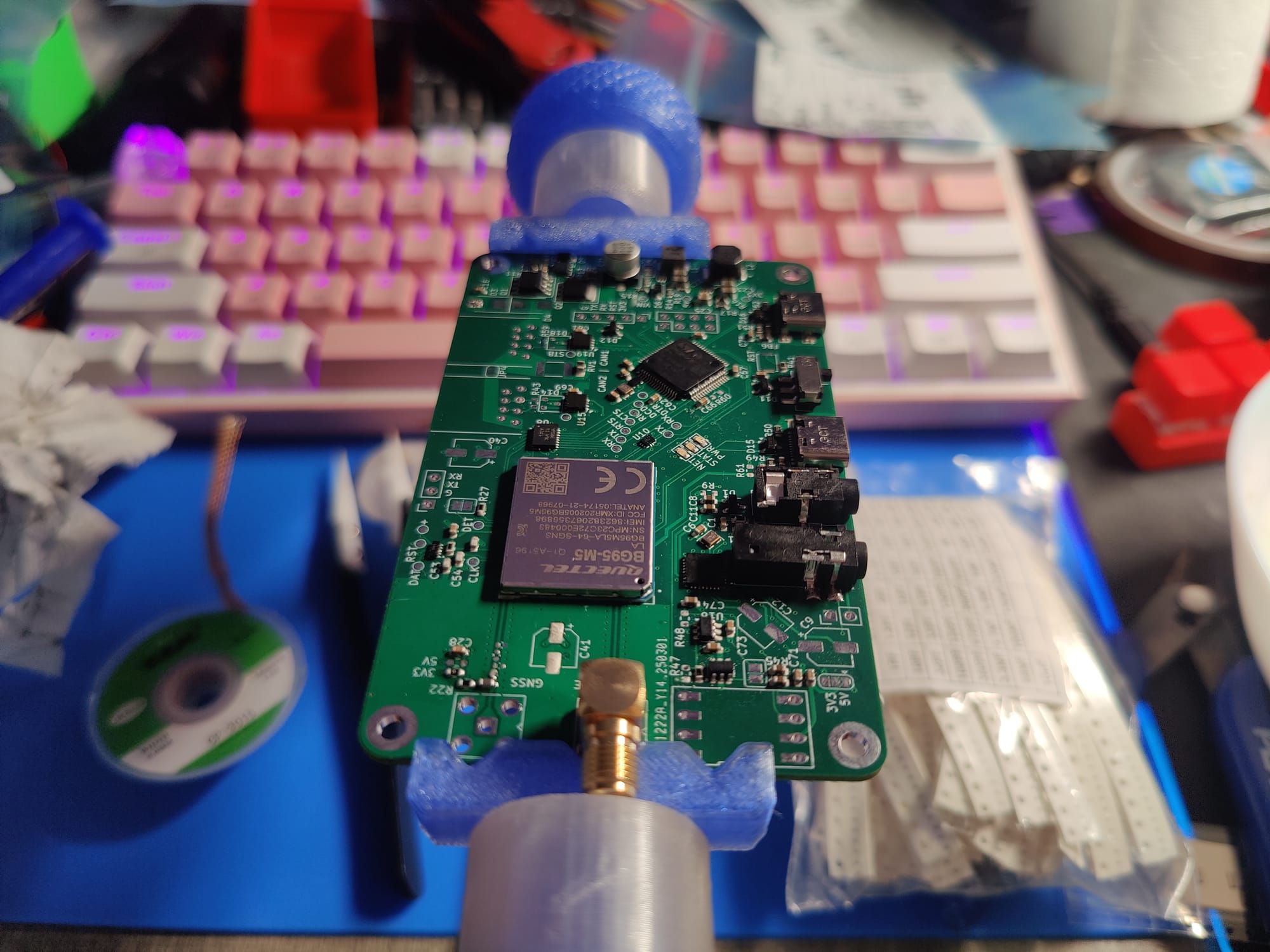
The second prototype is the one I'm currently working on. We decided on switching to a different modem since we didnt have any luck with the SIM7000E. For this design I picked the Quectel BG95 modem, since it is still fairly affordable and newer design with pin compatible alternatives available. Unfortunately however, to save some money and space on the system we would need to use a standalone modem SOC (System On Chip) instead of a module and so I would also have to design all the modem peripherals onto the board. Including the antenna routing which I was skeptical of from the beginning, I haven't had any experience or guidance from a professional on RF routing and our EE lecturer's advice was to just see what happens.
On this prototype my goal was to make use of all the techniques I'd learned from the past mistakes and push my limits yet again to make something totally out of my comfort zone work.
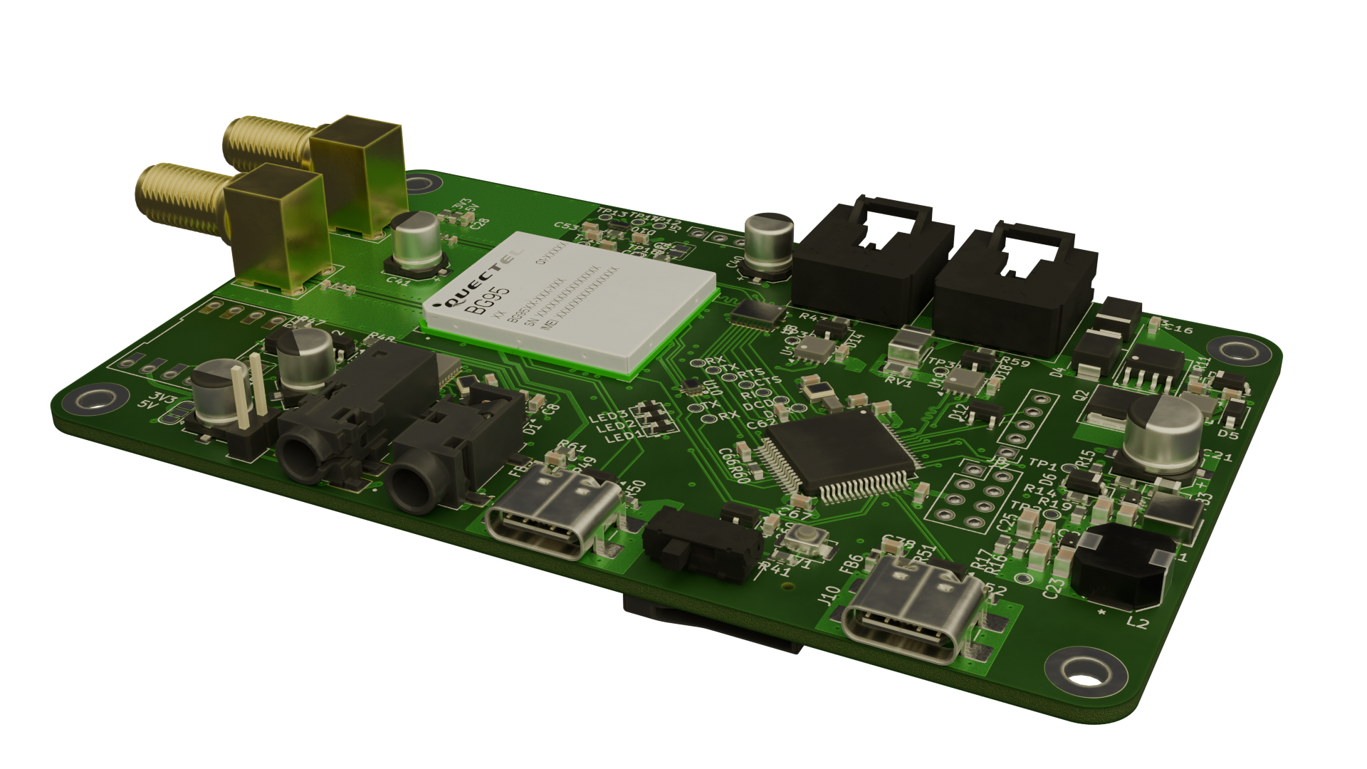
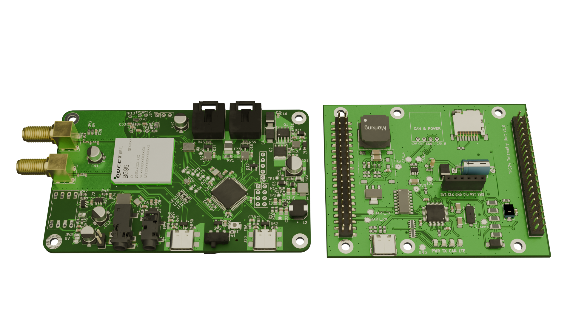
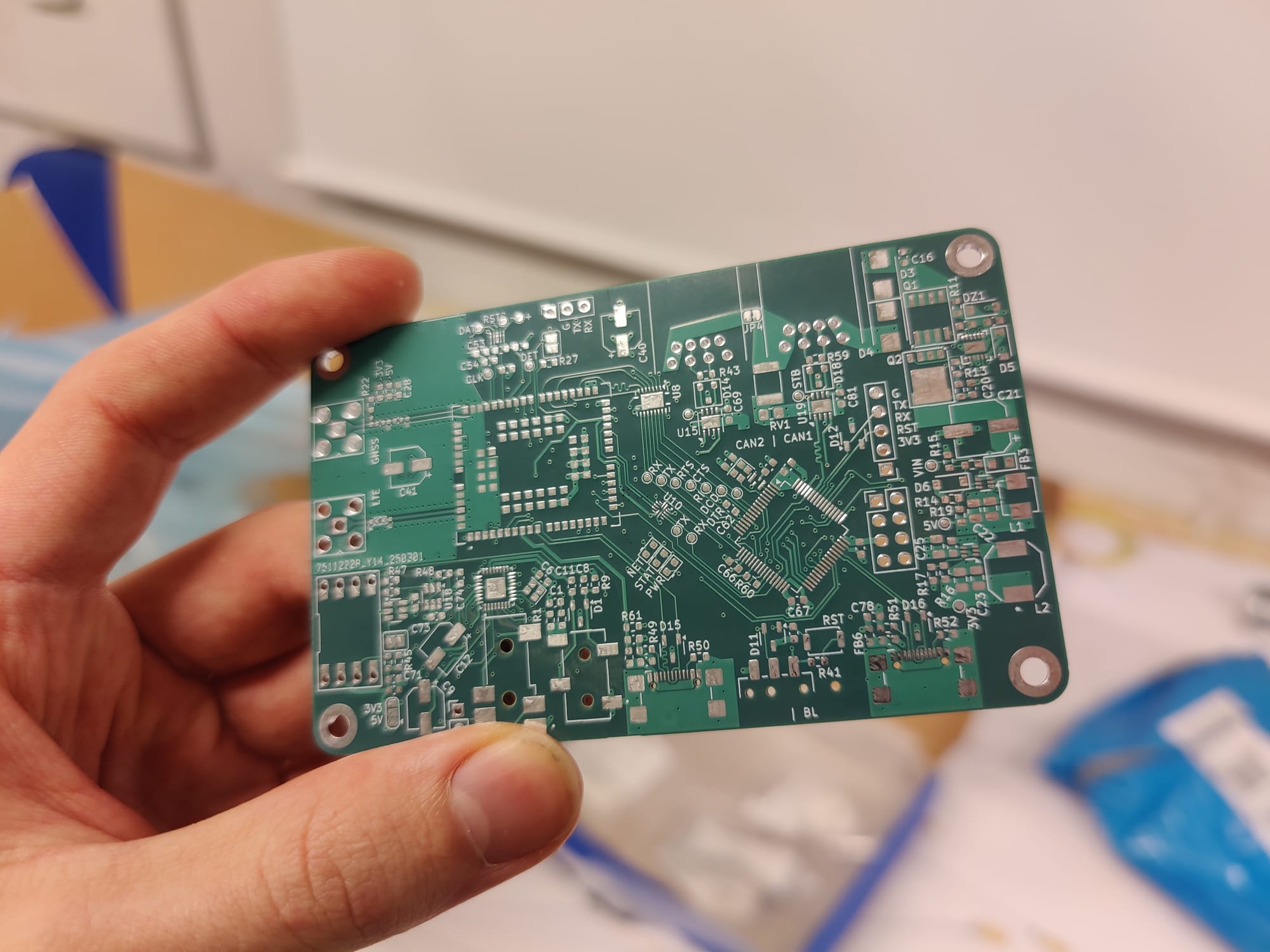
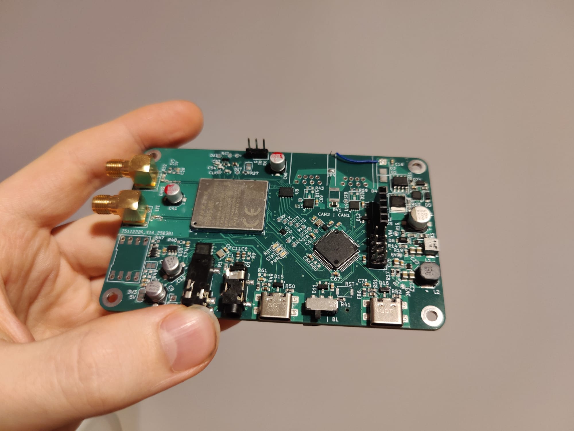
Overview of the new design
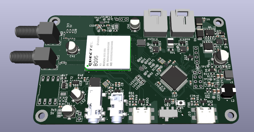

The modem used is the Quectel BG95-M5 along with an audio CODEC and the microcontroller I chose was the STM32H523 due to it having "modem control" UART, 2x FDCAN interfaces and ample RAM for buffering data. One of the additional requirements was also to include a differential air pressure sensor for a Pitot probe, so an analog frontend with level shifting for that was included on the board.
Most of the other components on the board are for power and interfacing with the modem. On the power supply I have used a Texas Instruments ideal diode with load dump protection for protecting the fairly expensive unit from various power line failures along with 5V and 3.3V buck converters designed to handle a theoretical maximum of 13 watts.
Last year we were experiencing some problems with the CAN transceivers, where they would suddenly stop transmitting and in some cases locking up the whole bus. Thus they were also changed on the new design, making sure they would be able to handle the FDCAN protocol and data rates of 1Mbps with the transceivers I chose handling up to 8Mbps, since we've had discussions of increasing the data rates. As of now we are still using the classic protocol with 500kbps data rate.
Server side
The Node.js API still stands and has continued development, however a new database and a new front end for data visualization has been chosen following some recommendations.
The recommendation I got for the database was InfluxDB, with it being designed to handle time series data, the same kind which we collect from the car.
And the recommendation for visualizing the data was Marple.
Currently I'm hosting the database and API on my own machines. Locally hosting it on the same machine as the API has its benefits in removing additional latency, but the whole server setup will have to be moved to a separate provider eventually.
As of now the server side works as intended and the communication between API, database and front end has no issues. The progress of the system is now hanging on getting the hardware working.
Assembly
After the boards had been designed, they were quickly ordered to start assembly and testing, hoping that everything works and knowing it rarely does. Any mistakes in the design will have to wait until next year since our electrics department is severely under funded and new designs will have to wait for next year's budget.
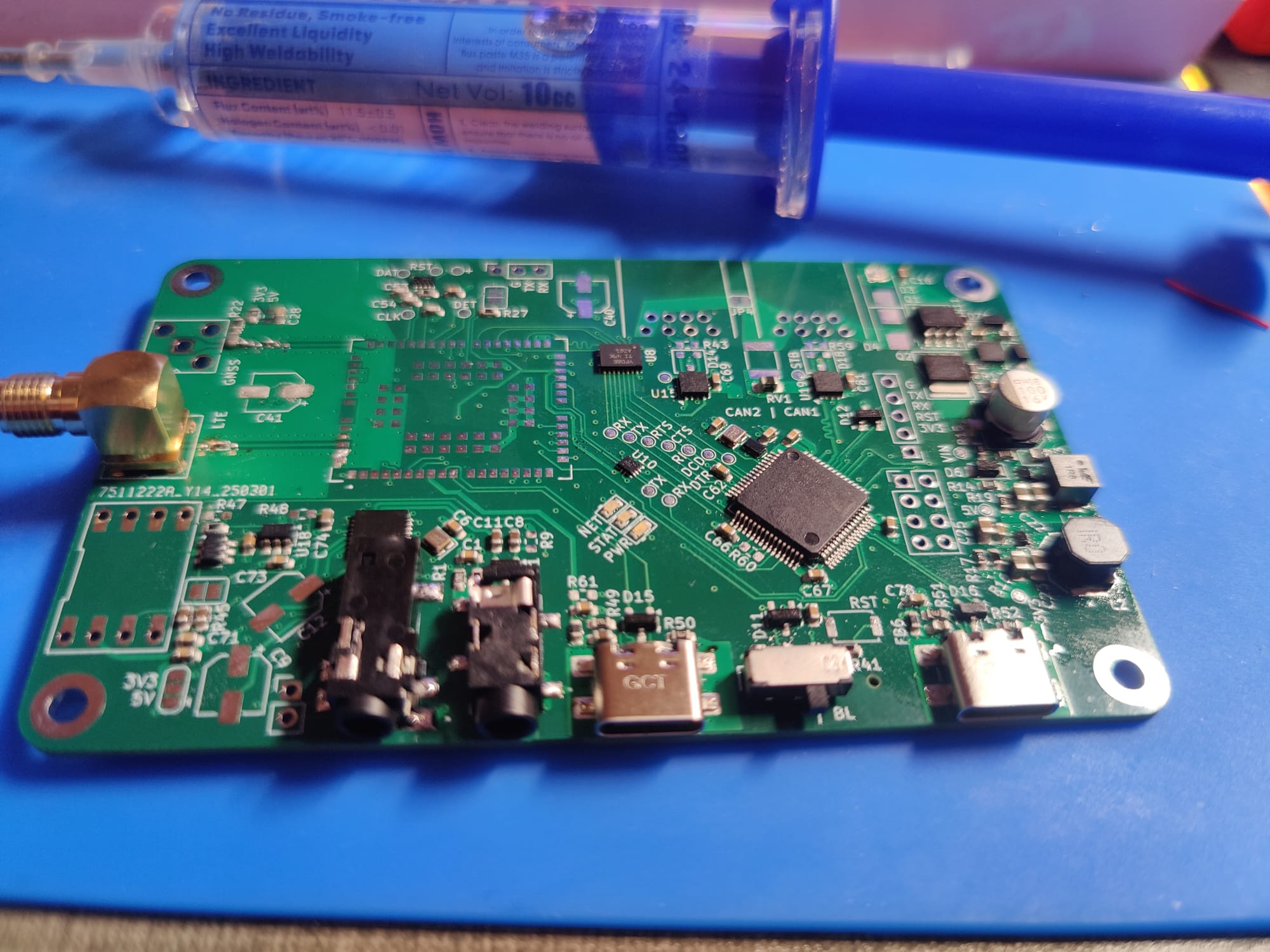
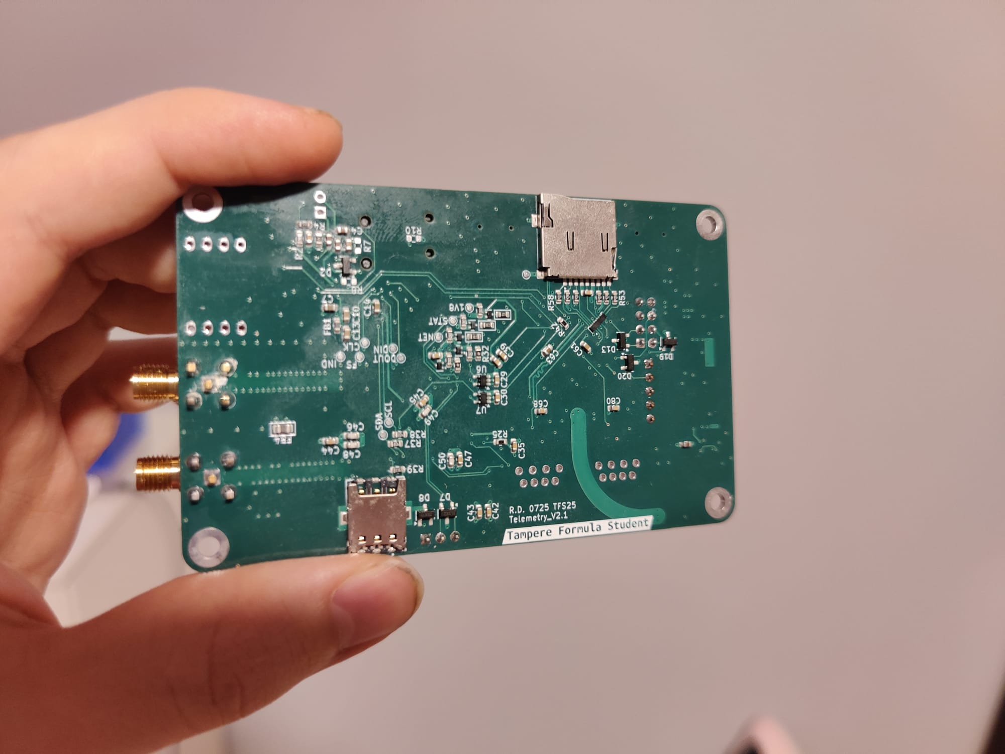
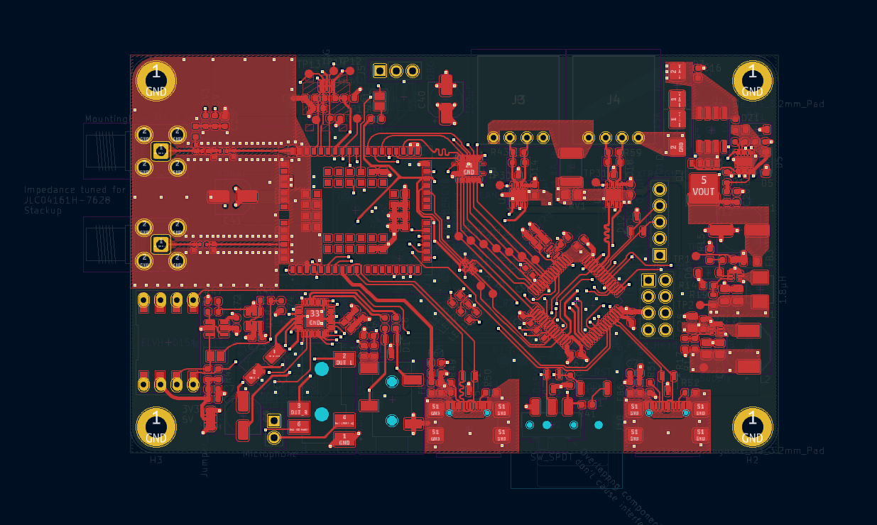
Manual assembly was very difficult and tedious with over a hundred components smaller than a grain of rice. Trying to find a dead short between 3.3V and ground took some time and ended up taking the better part of two days just to get everything assembled and working enough to start developing firmware.
Testing the hardware
One of the first things after getting the boards from the PCB manufacturer, was for me to check if the antenna routing was usable or not. As standard with the school, I was given the 30 year old equipment and wishes of good luck to figure it out myself.
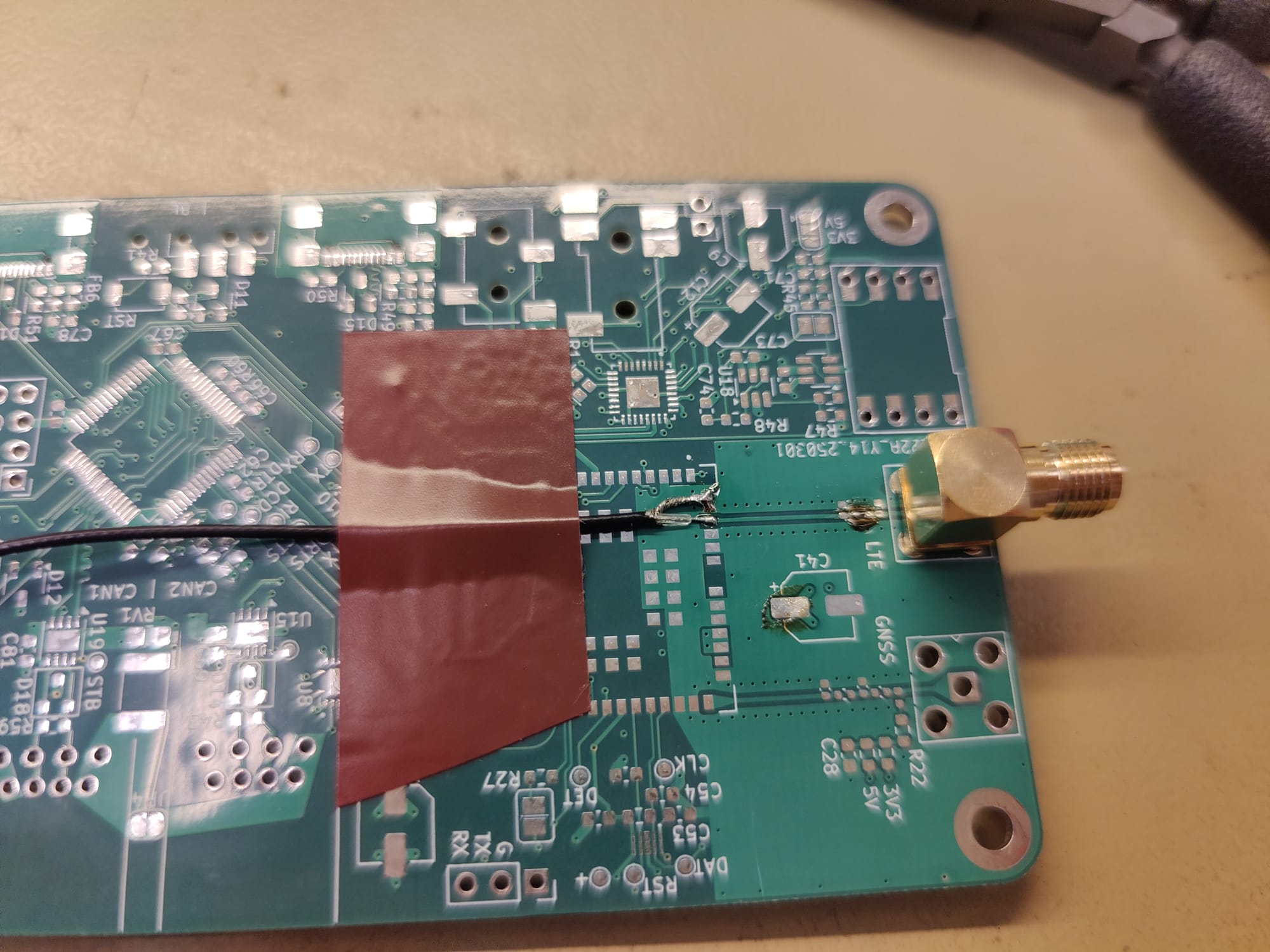
There was no other equipment for hardware testing than the leads and connectors to interface with the various equipment used for course material. All of the school's RF equipment used BNC or N-type connectors with a total of one SMA cable found in the lab, this was still enough to connect the board to the test equipment.
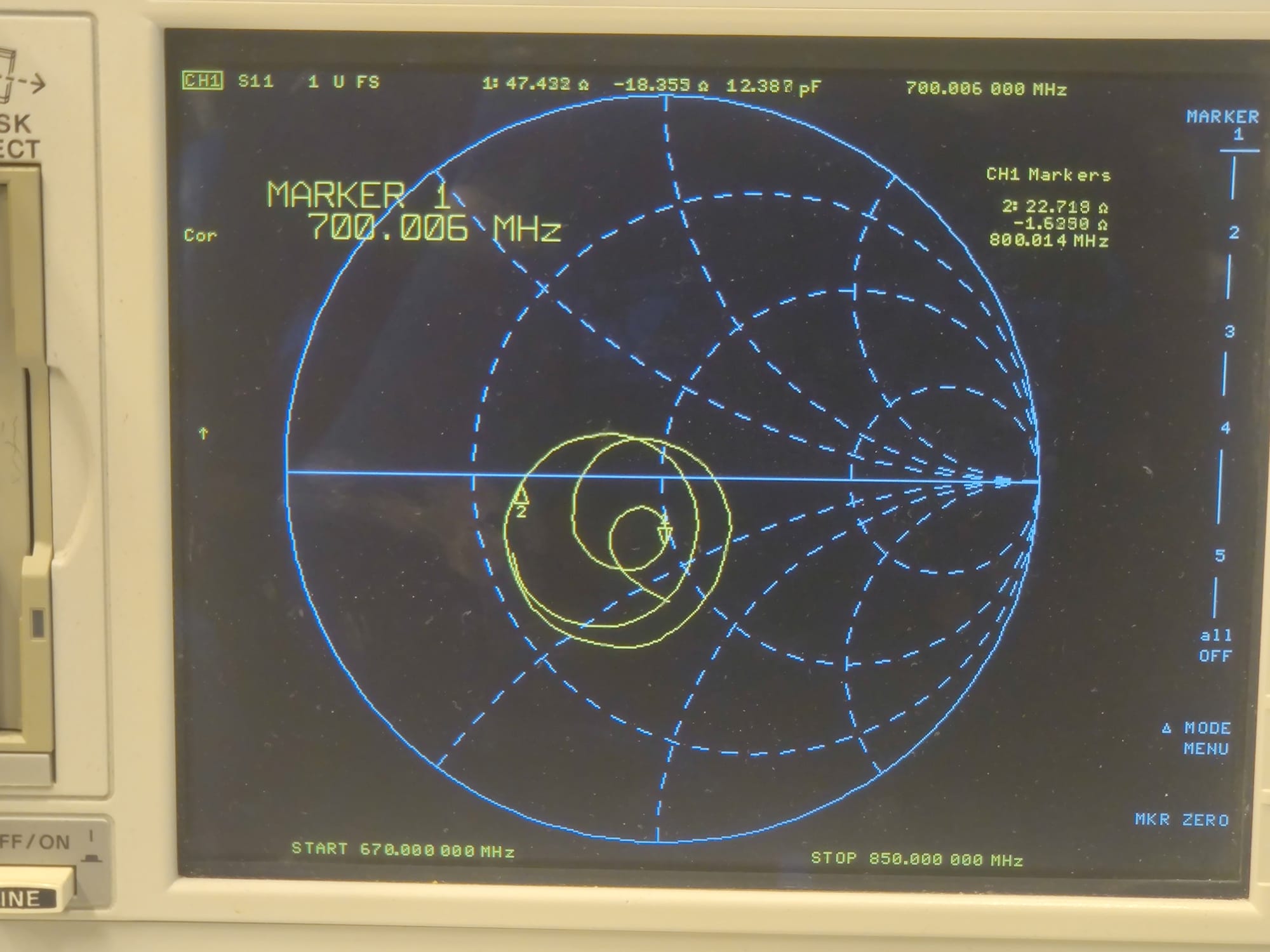
I didn't know of any proper way of measuring the trace impedance or interfacing with the SOC side of the trace, so I ended up stripping one of my MCX to SMA adapter cables, keeping the SMA end and soldering the stripped end onto a spare board. After calibrating the leads I got some measurements from the VNA (Vector Network Analyzer) to analyze later, since I still needed to figure out what I actually needed to do to correct the impedance mismatch.
Blink
Quickly after flashing the first blinky on the board, I realized I'd made a mistake, this time with choosing the STM32H5 series microcontroller. I had not known of this during the design phase, but this particular MCU is designed to be used with the Azure "ThreadX" real-time operating system, and the only realistic way of using the USB interface is by using that, or not using USB at all. Good thing is that USB is not mandatory for the system to work, just hoping other peripherals won't be limited in the same way.
As of now this is all I have, development still continues all the way up to the competitions and I will follow up on the projects as progress gets made.
Thank you for reading!