Suspension Force measurement using Strain Gauges
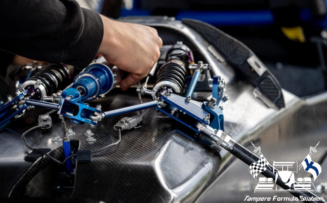
In this post I'm going to go over my process of the development of a suspension force sensing system for a Formula Student race car.
Suspension rods
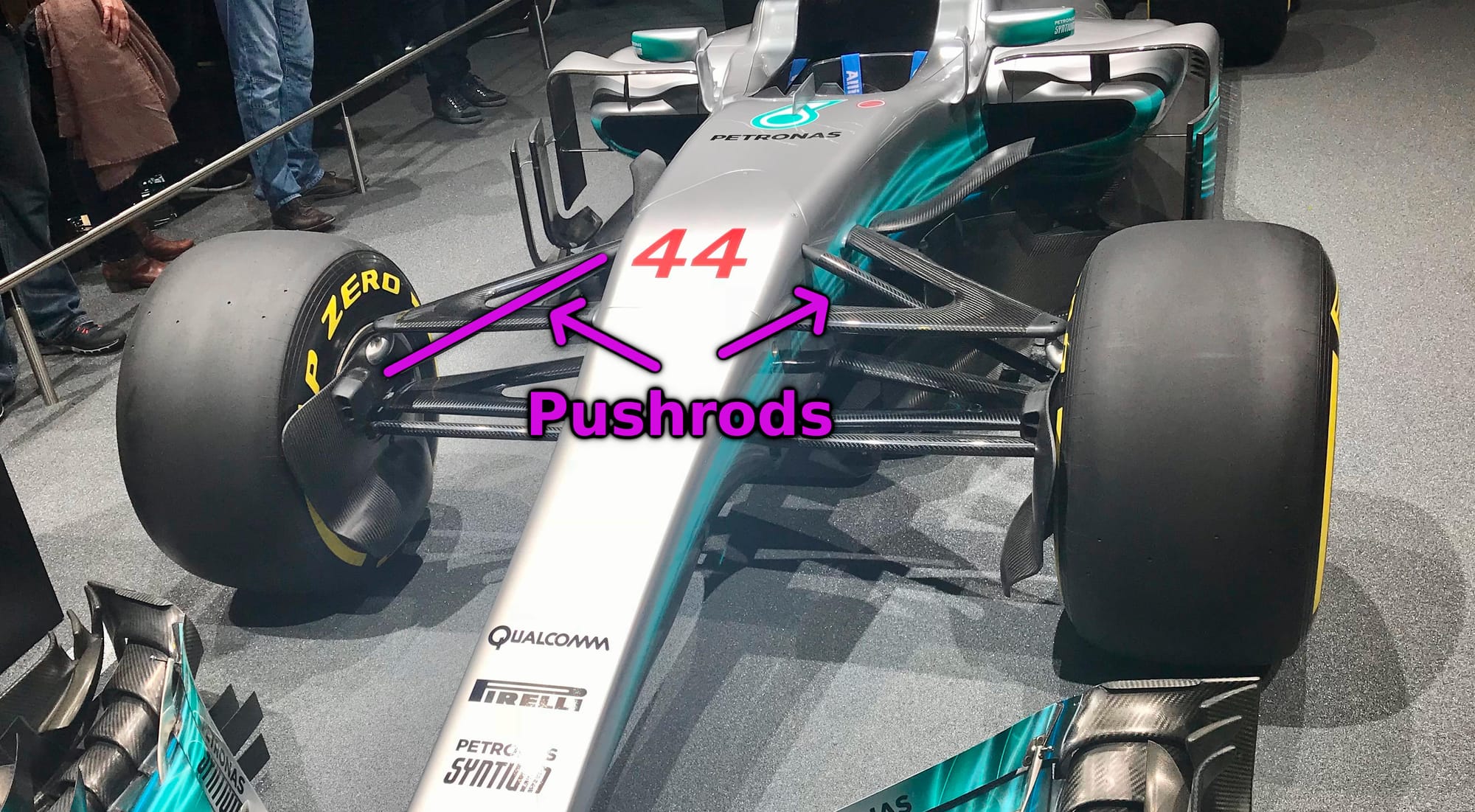
The suspension system of a race car is an engineering feat in itself and in this post I won't be going into the details of it too much, however we need to understand what we are working with.
One suspension rod configuration is pushrods, as the name may suggest, they transfer the suspension loads from the wheels to the load absorbing elements located within the aerodynamic covers by pushing on a rod, often made of carbon fiber. Another common configuration for suspension force transfer is the pullrod configuration, but in either case, the forces are transferred through a rod, onto which we can attach our sensors to. Speaking of our sensors..
Strain gauges
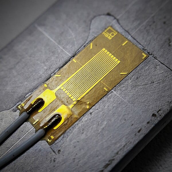
These little devices are strain gauges, also known as FSRs or Force Sensitive Resistors, they are made of a film that holds a length of resistive wire. These sensor elements are designed in a way, that they change their electrical resistance based on the length of the resistive trace. By shortening the length of the trace, we can decrease it's resistance and vice versa. This means that if we rigidly attach the film onto the surface of an object, it should deform just as much as the object it is attached to. Knowing the gauge's specifications and the material's properties that the gauge is attached to, we can determine the object's deformation based on the change in the strain gauge's resistance, and further calculate the applied force needed to deform the object the measured amount.
Measurement
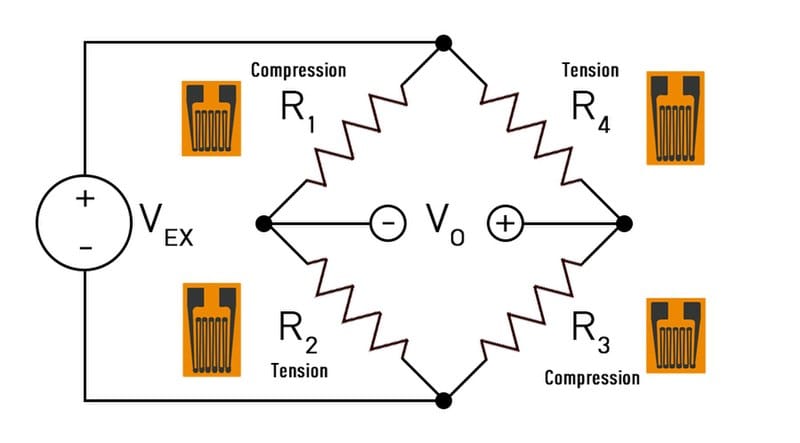
In order to measure the strain gauge's change in resistance, we first need to somehow convert the change in resistance to a change in voltage. This can be easily done using a Wheatstone bridge.
A wheatstone bridge can be thought of as two separate resistor voltage dividers. In this case looking at the above image, the first voltage divider would consist of the resistors R1 and R2, and the second voltage divider consisting of the resistors R3 and R4. The output VO is the difference between these voltage divider outputs.
If we look at the a single voltage divider and assume both resistors to be identical, we can expect the voltage divider output to be exactly half of the excitation voltage VEX. If the second voltage divider also consists of identical resistors and the output being the difference between the two voltage dividers, we can expect the output voltage to be zero. However changing the resistance of any single resistor will cause the voltage divider's output to change and now assuming the other voltage divider is still unaffected, there will be a difference between the two voltage divider outputs that we can measure as a voltage!
Amplification
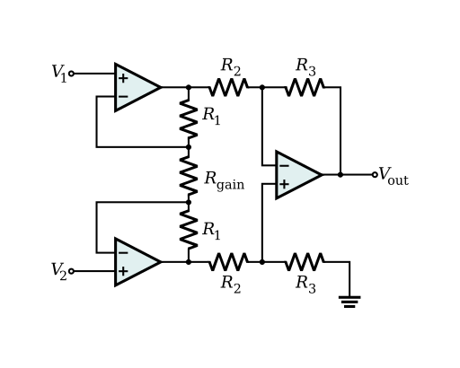
Even though we have now successfully converted the change in resistance to a change in voltage, since we are measuring the deformation of a material, we expect the signals to be very low voltage, usually in the millivolt range.
A popular way of amplifying the differential signal is using an instrumentation amplifier (In-Amp). Since instrumentation amplifiers only amplify the differential signal, rejecting the common mode voltage, which in our case is half of the excitation voltage, we are left with only the amplified difference between the voltage dividers formed by the wheatstone bridge. Another benefit of the In-Amp common mode rejection is the rejection of noise that might be induced onto our analog paths by other devices, since its fair to assume both signal traces to be affected equally.
Circuit design
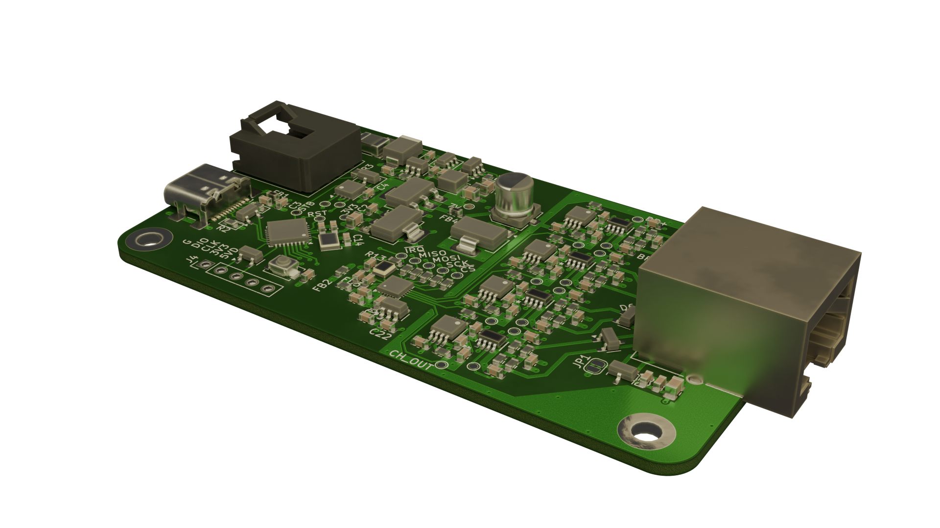
Finally its time to implement the theory into practice. Our circuit needs to be able to convert a number of analog measurements into digital format and transmit them over the car's sensor CANbus to be monitored by other systems.
I've decided to implement four channels on the board to be able to get multiple separate measurements from the suspension rods, for example compression, torsion, bending etc. if the need arises. Individual channels also make it possible to use varying gain factors between the channels to account for different amplitudes in applied force.
Each input is ESD protected and buffered to help protect the measurement inputs from possible static built up by the tires while driving. For the In-Amps I've chosen the Analog Devices AD8227, which is well suited for tightly packed and fully enclosed designs.
The analog to digital conversion is done with Microchip's MCP3564 24-bit Delta-Sigma ADC, which I've chosen based on it being one of the only available high resolution 4+ channel ADCs that wouldn't drive the team into bankruptcy.
For the connector you might have already noticed the RJ50 socket. My idea was to utilize pre-existing shielded networking cables and the shielded 10c10p RJ50 for easy connection and disconnection of the sensor leads during testing and dry environment use. For use in the car, the connector will be swapped for a panel mount waterproof connector that will be attached to the enclosure.
Closing thoughts
This project has been and will continue being a massive learning experience into instrumentation and product design as we progress on to manufacturing and testing the circuits. It is a real challenge trying to think of all the possible things that may or may not go wrong when you're designing something new to you. Our current method of project design doesn't allow for a lot of prototyping, which can be a bit nerve wracking when designing more complex circuits. This circuit isn't particularly complex, but it is the first time for me designing this type of analog measurement unit, however I do feel fairly confident in my design. Let's hope it works, but I will post an update on the results regardless 🙂.
Thank you for reading!


